
Vatech Case Study · Implant placing
We have already explored the undeniable advantages of 3D CBCT technology in implantology in the last article, the first part of our series dedicated to this elaborate field of dentistry. We learned how to use our powerful software, Ez3D-i, to plan implants – with mandibular canal drawing, bone density qualification, and distance measurement. Today, we will talk about the process of choosing an implant and editing it to ensure the best and safest implant placement process.
The key features that we will talk about today are:
1) Insert Implant
2) Implant checking
a. Set MPR Axis
b. Implant Bone Density
c. Implant information
d. PRO TIP: Multiple implants
3) Implant Property Tab
4) Implant placement options
5) Implant adjustments and preparation for CAD/CAM
6) Consultation Tab
1) Insert Implant
Inserting implants into the 3D Image is fairly easy – after finishing the implant preparation process and making the correct measurement in the area of the future implant, we can right click the measurement line and choose “Insert Implant”.
Our AI will process the measurement and carefully recommend 3 different sizes of the implants – a size which is slightly smaller than your measured distance, one that is just right, and one that is slightly larger for the measurement that you have prepared. The AI tool will also offer you suitable implants from your favorites tab, which ensures true convenience.
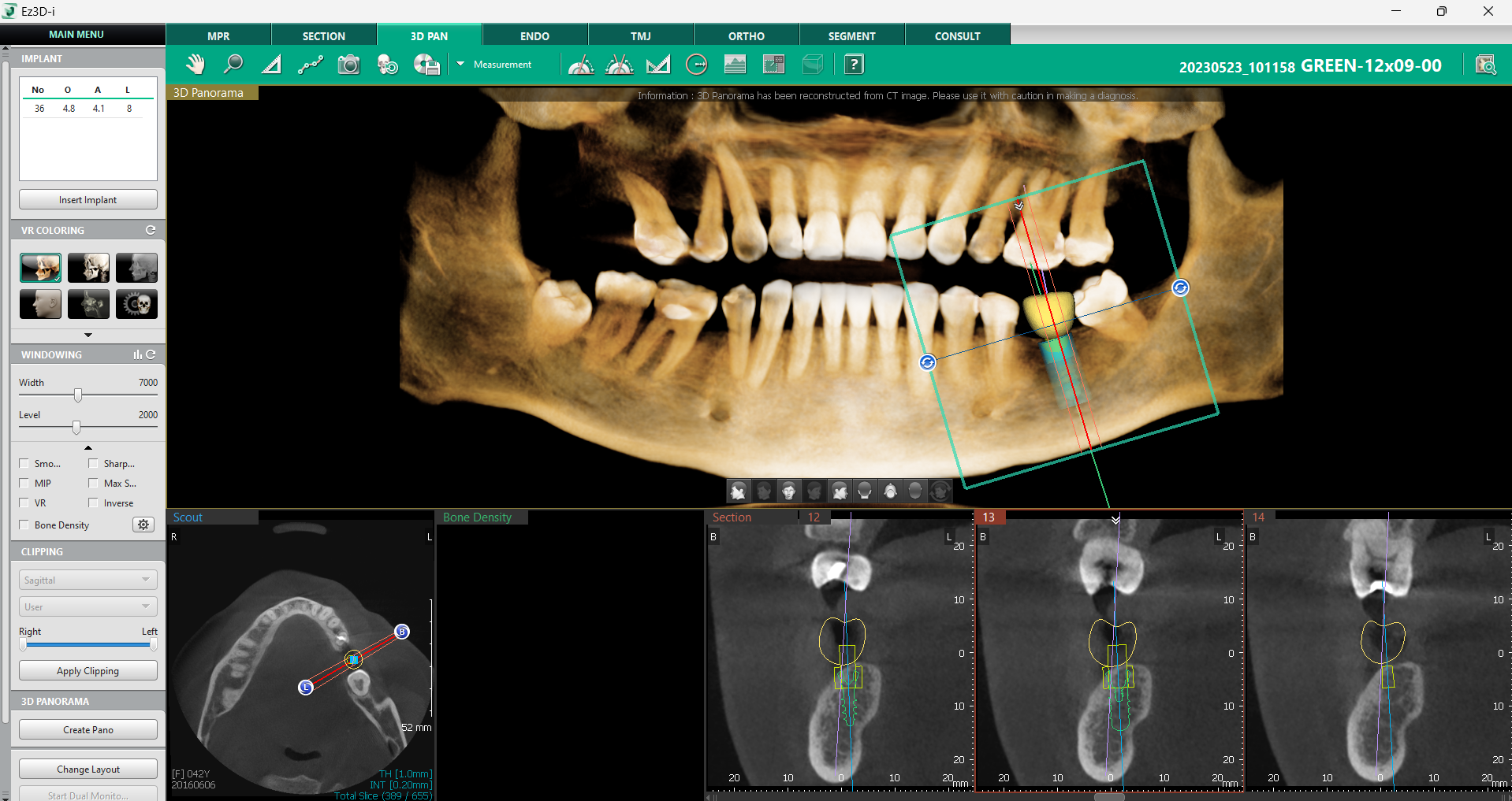
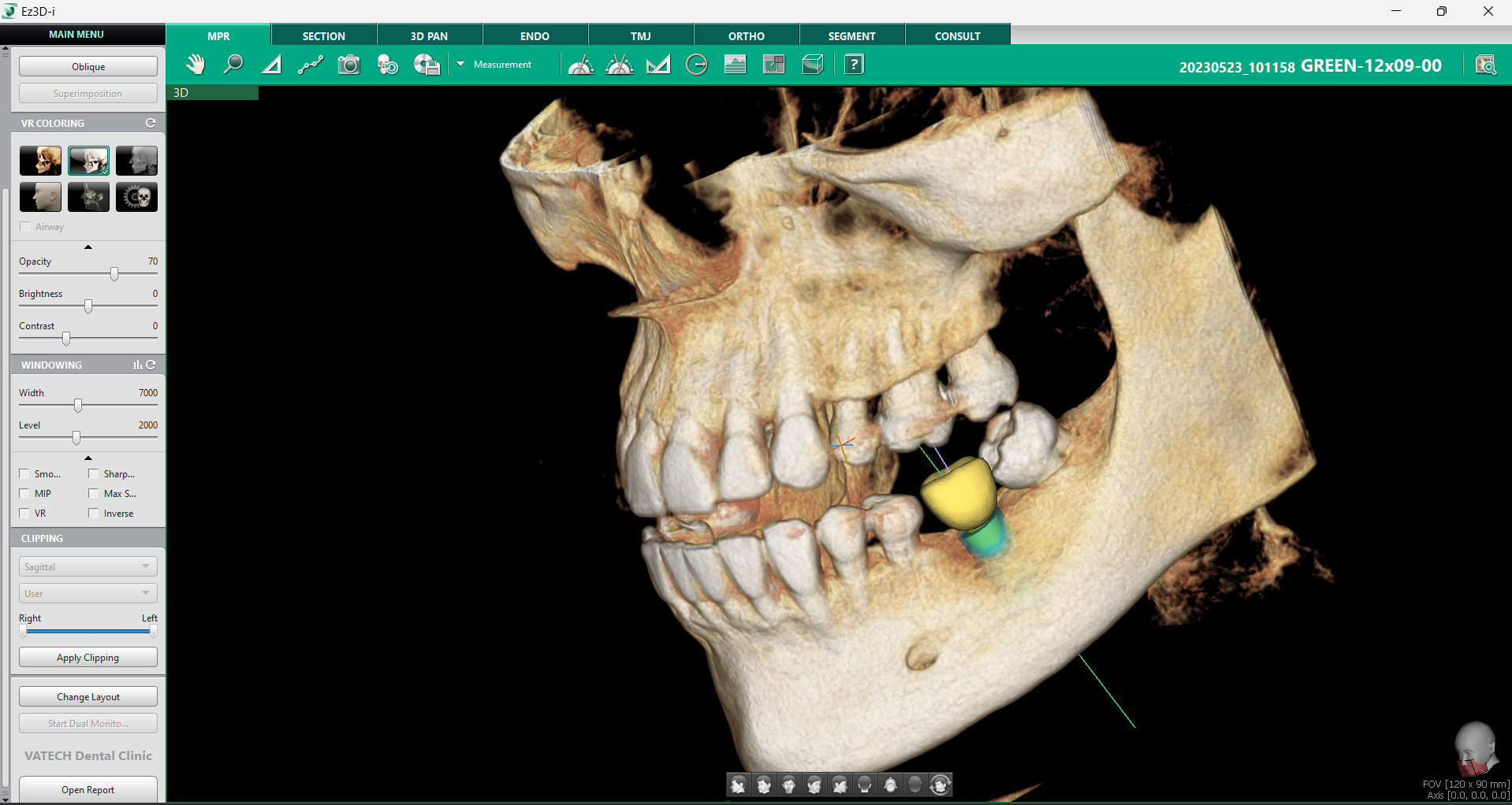
After you left-click the size that you like, a model of the implant will appear in the 3D image immediately.
2) Implant checking
In implantology, there is no such thing as checking too much. Multiple different ways of checking the area of the implant can be a deciding factor in whether or not the implant will take to the bone nicely. Ez3D-I has been designed with that in mind and offers multiple tools that make double and triple checking the position during implant placement as easy as possible.
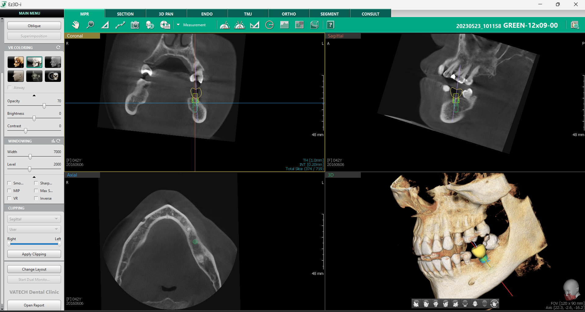
a) Set MPR Axis
Set MPR Axis is a handy tool when it comes to checking the correct placement of the implant. It makes checking the bone health and the implant’s position within the bone possible with only one click.
While in the MPR tab, right–click the implant and choose the “Set MPR Axis” option. The software will automatically set all of the image planes on the implant.
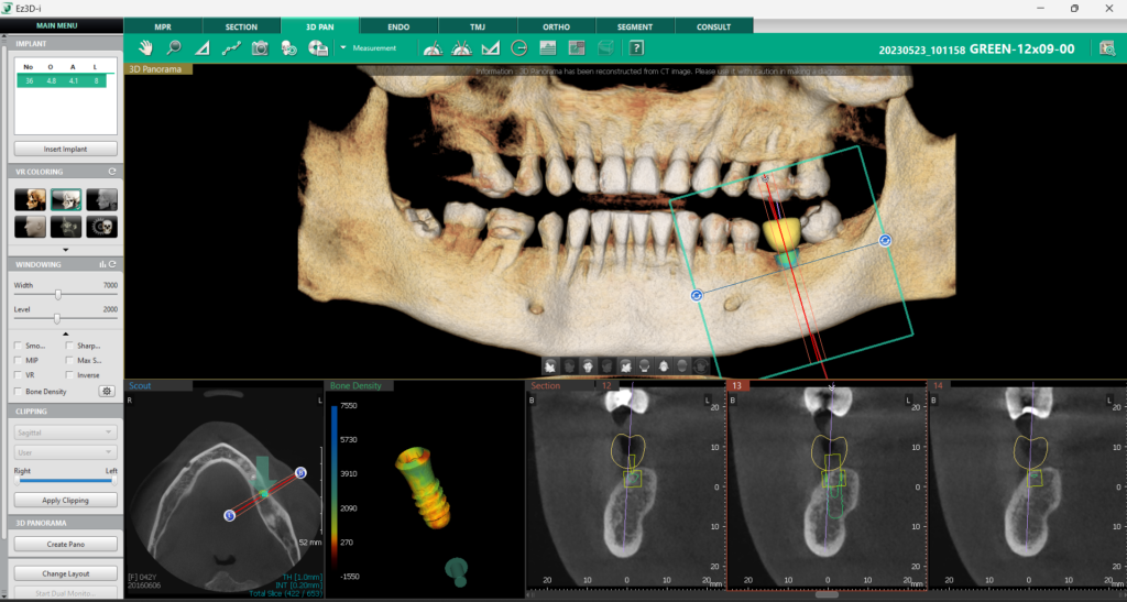
b) Implant Bone Density
We have already covered a lot of the many bone density qualification tools that Ez3D-i offers in our previous article about implant planning, which you can read HERE. This particular bone density qualification tool shows the density right on the implant for one last check.
This tool is available in the 3D Pan Tab after clicking on “Change layout” on the left lower part of the screen and choosing a layout with “Implant Bone Density” window.
After you left click the implant you want to check, a graphic model of the implant with a colorful overlay corresponding to the D1 – D5 scale will appear. You can freely move the model around and check it from all sides to make sure that everything seems ready for the implant.

c) Implant information
It is always useful to gather as much information as possible about the implant. It can make it easier for you and your staff to get ready for the procedure and to keep track of all the tasks. The MPR view gives you an option to get all the information about the implant in two click – right click the implant and choose “Show info” to get all the information you might need about the implant – including the line-up, type, length, etc.
Once you no longer need to see the table with all the information, you can click the implant again and choose “Hide info”.

PRO TIP: Multiple implants
If you have a patient with multiple implants placed in your 3D image, it can be tricky to navigate everything. Ez3D-i has a simple solution: if you are in a 3D Pan Tab and you have multiple implants placed, there will be a small section called “Implant” on the left top corner, where you can quickly click through all the placed implants.
4. Implant Property Tab
Implant property tab is one place in the implantation process where you can adjust almost everything about your implant. It is accessed after right clicking the implant and choosing “Property”.
The first option you have in this tab is choosing between a single implant or multiple implants. This makes the placement of restorations easier. You also see which tooth is the implant in place of and can change the number of the tooth according to your needs. The model of the crown will reflect the changes immediately after you click “Ok” at the bottom.
On the left side of the window, there are four ticks for different parts of the model – Implant, Implant Guide and Path, and the Crown. You can choose if you want to see them in the image and freely choose their fully customizable colors.
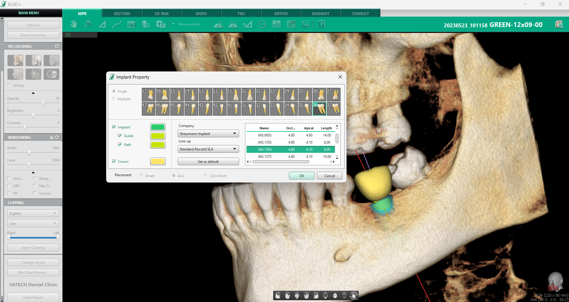
Next to it, you can choose the company and implant line-up. If you have a favorite option, you can set it up as default so that the AI can recommend your favorite implants the next time you want to place an implant. The database has information about all the main manufacturers and is updated regularly, which can be done with our authorized distributors.
The table on the right offers you the available implants corresponding to your chosen company and line-up.
a) Implant placement options
We used the Implant Placement by Measuring Length option in our case, but the system allows other ways of placing an implant too – you can use the help of AI.
If you want to use the smart options Ez3D-i has to offer, go to the MPR tab and choose “Insert Implant” out of the Simulation menu on the left top corner of the screen. After doing so, a property window will pop up – the same one that we opened through the placed implant.
You can very easily choose if you want a single or multiple implants and pick the number of teeth that you want to replace.

On the very bottom, there are the options that you can choose from – Smart placement, Placement on an Axis, and Click Point Placement.
Smart placement will automatically insert the implant based on the number of the chosen tooth. Placement on an Axis will automatically insert the tooth based on an axis. And the Click Point Placement option will change your mouse cursor into an insertion mode and place the implant automatically at the point where you clicked with your mouse.
The Implant Placement by Measuring Length option which we did in our video, cannot be done with the “Insert Implant” button.
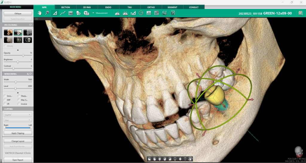
5. Implant adjustments and preparation for CAD/CAM
The software has multiple options for making small adjustments to the implant. For more control over small changes to the position of the implant, you can use the controller. There are two different ones – one for the implant itself and one for the crown. Right click the needed part of the model and choose show controller. With the controller on, you will have way more control over the small adjustments and will be able to place the implant perfectly.
Another option lets us change the size of the implant. If we want to size up or down the implant, all we must do is right click it and choose “Edit implant”. We will get a pop-up window which lets us adjust the length, occlusal size, and apical size. The changes will happen in accordance with the chosen implant line.
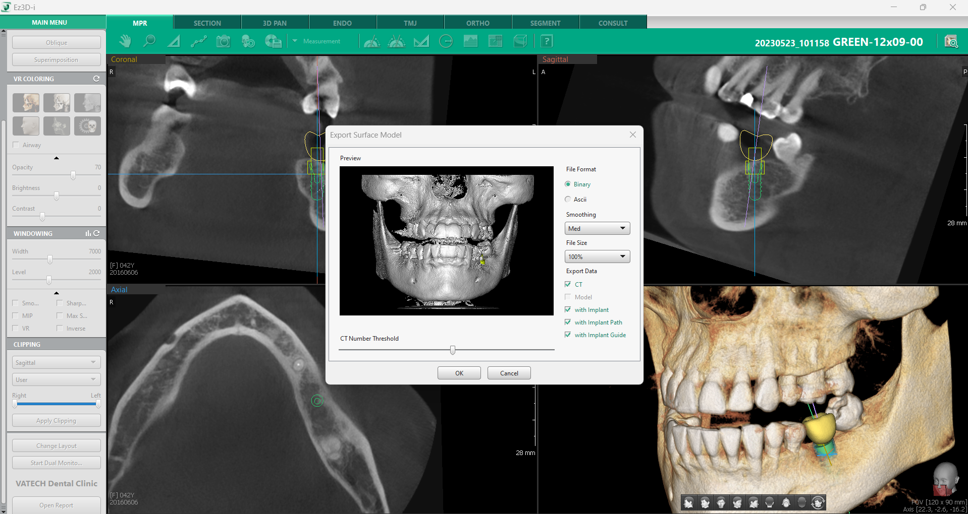
Once you have finally adjusted everything and settled on final implant size and placement, it is time to export everything into CAD/CAM. It is very easy to do so by going into the Main Menu and clicking “Export Surface Model”. The dialog window guides us through the process of exporting the data – we can choose the file format, smoothening, file size, and which data we want to export by ticking the corresponding options.
6. Consultation Tab
Implantology can be a scary procedure for patients, so it is crucial to have an easy and effective way of communicating the procedure details to patients. Ez3D-i offers a “Consult” tab which caters to all the consultation needs.
The left side of the tab shows all screenshots, images, and other materials, that you prepared, while the right side shows educational videos provided by Vatech. The database offers over 250 videos from various groups which you can choose from on the left.

Here is a quick overview of how we used the functions mentioned above to do a diagnosis of the patient.
If you have any pointers or questions, please, contact us, we would love to get your professional experience on the matter of diagnosis.
For more Clinical Cases, please click here.